The story of cover: 1969: ARPAnet from 4 nodes.
Kinds of Network
Network is used for communication between communicable devices. No matter the scale of network, when we connnect our computer to the router in our home, a network has already formed.
LAN
LAN is a kind of network for private use, such as office in company/campus/building. Depending on the requirements of the network, the scale and functionality might be huge different. Each device in LAN has a unique identifier to prove their identity in the LAN and communicates with the specific device.
WAN
On the other hand, the range of geography of WAN is usually larger than LAN. It is for public use, connecting with cities, states and even nations. However, the scale of the network is not the proof whether a network is WAN. The difference between LAN and WAN is how devices connect: LAN makes different host connect with each other, but WAN connects different network devices, e.g., network router. In other words, LAN is consisted of devices, and WAN is consisted of LANs.
There’s two kind of WAN: point to point and switched.
|
|
Internet
When two or more than two networks connects, then internet formed. Nowadays, WAN and LAN are usually connected together.
For example, if a company has two offices (A and B) located in different region, each office has a LAN to connect all computers in the office, and two offices need to be connected as well, so there are two LAN and a WAN, which is a internet.
The Internet
The Internet is another concept here, which is special and unique of internets. It connects thousands of internets around the world.
Hierarchy in The Internet
There are three different tiers on the internet.
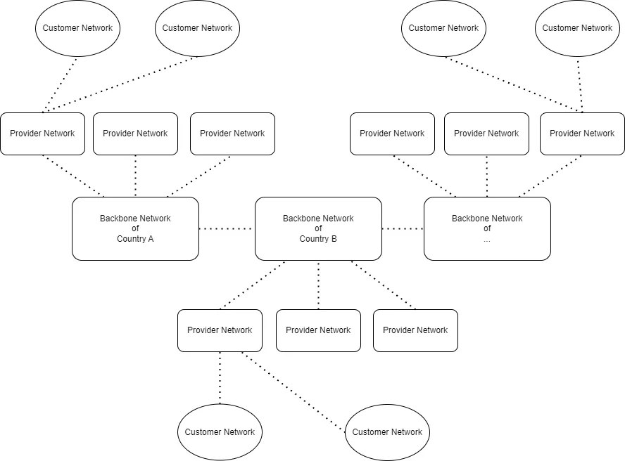
Backbone network, they connects internets of different regions and nations, which is usually owned by communication company. Backbone network is not unique, for example, one country might have one backbone network, and different backbone network of countries connects by a complex switch system. We called the complex switch system “peering point”.
Network provider paid to communication company for using some services in backbone network, which is called provider network. And then, customers paid to network provider to use the internet.
Backbone network and provider network are called ISP, they serves the internet services around countries or regions.
Network Protocol
When we talk about network, we always heard about “protocol”. Protocol makes the process of data sending/receiving divide into different layers. Once the means of communication has changed, we just need to replace related layer/layers in the protocol rather than the whole design, which means easier to maintain and reusable.
Basic Scenario
We can simplify the model of communication into 3 necessary parts:
- Create/Obtain Data: there are always need someone create and obtain information.
- Encrypt/Decrypt Data: to make sure the safety of the information during transmission (no leakage, no replacement).
- Data Transmission: be responsible for transmission process.
For example, if Maria sends a mail to Ann:
- Maria write the content of the mail. (Create data)
- Maria put her mail into envelope. (Encrypt)
- Maria send the mail by post (Data transmission)
- Ann get the mail and open the envelope. (Decrypt)
- Ann read the content of the mail. (Obtain data)
As the development of technology, Maria doesn’t need to send the mail by post anymore, while she might use email for instead. Even all parts are different, but the purpose of each part hasn’t changed. Once we change the implements of related parts, the protocol can work again.
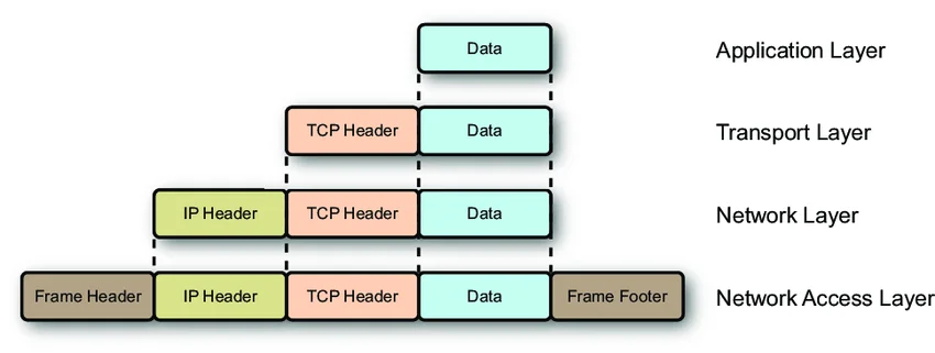
TCP/IP
This is the protocol we use on the internet. Just like what we mentioned above, it is split into different layers, and each layer will handle a specific kind of tasks.
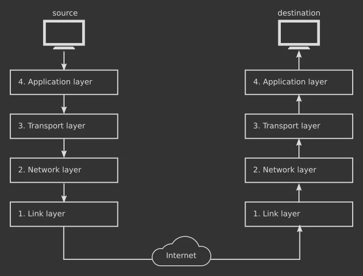
Layers in TCP/IP
| Layer Name | Use of the Layer |
|---|---|
| Application layer | The application we use, which generate and receive data |
| Transport layer | This layer is to determine the means and detail of transmission. |
| Network layer | Find the location of target, lead the data to the right place. |
| Link layer | Handle the process of transmission. We can also call it access layer. |
Although there are 4 layers totally, in fact, not all devices need to handle traffic of all layers.
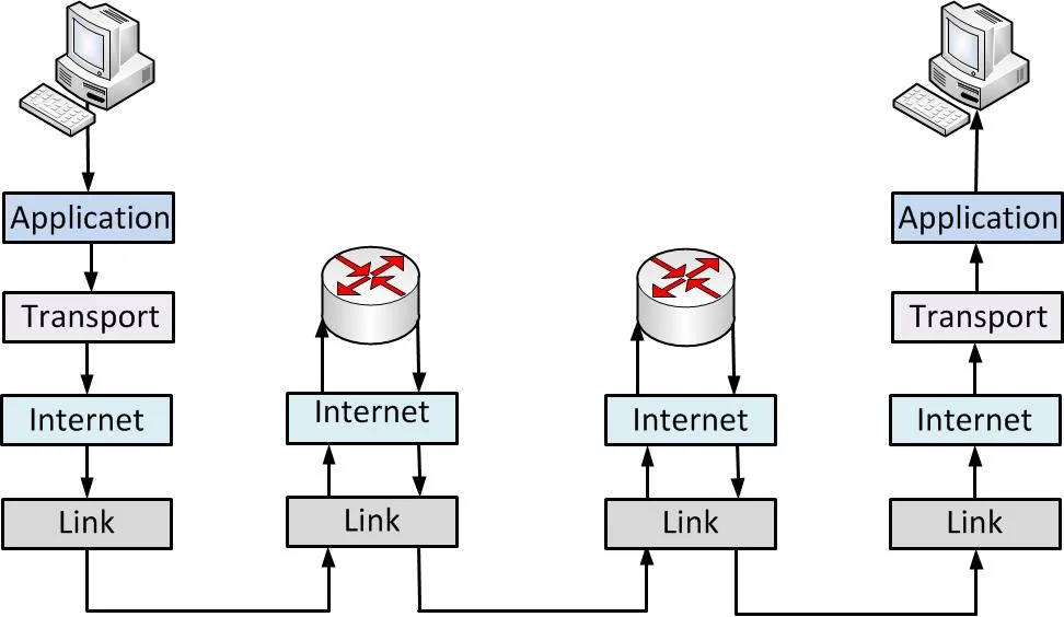
For example, for routers of network providers, absolutely, your data will through these devices, but they don’t need to know the content of your data (and they shouldn’t). That’s why internet layer is enough for them (they need to know the destination of your data).
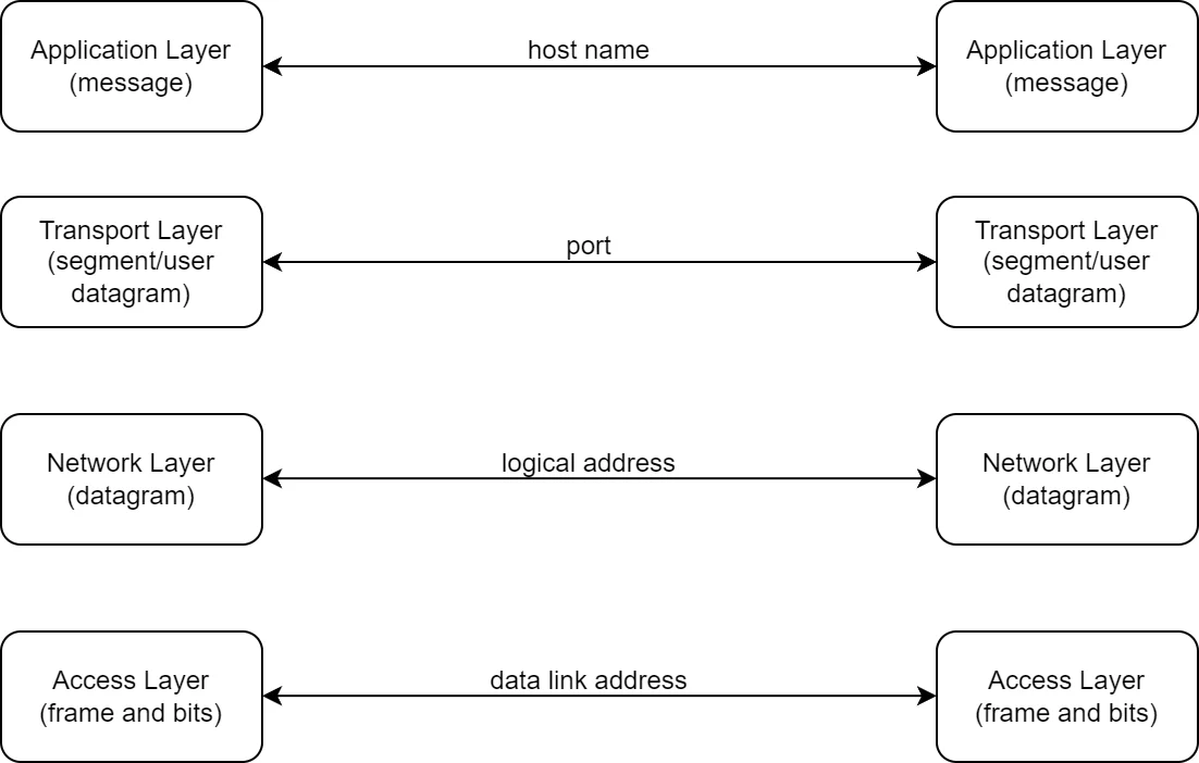
Address and Data Packet
According to the graph of end to end, whether receive or send, the same layer will handle the same kind of information (check data packet in each layer), and each layer has its own identifier to communicate (check data address in each layer).
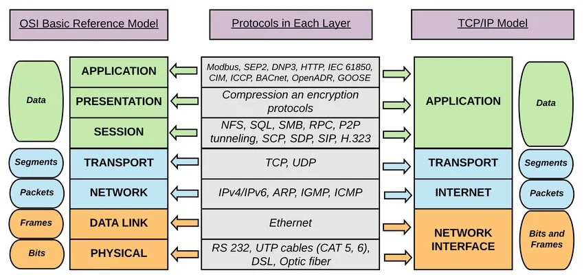
OSI Model
OSI model is Open Systems Interconnection model, which is a conceptual model. It devides layers of network according to its functionailities in more detail, and it and TCP/IP can transform to each other. In this post, I will focus on TCP/IP model, so I might write another post to introduce layers in OSI model in future.
Application Layer
Application layer is the most flexible layer in TCP/IP because it work on transport layer and no layer works on it. If the implement of application layer doesn’t work, you can replace it easily using another implement. It also the layer that is the closest to user/server, sending and receiving message.
There are two kinds of work mode: client-server and p2p.
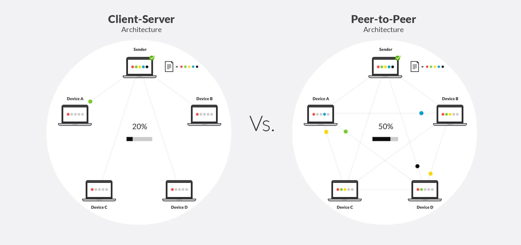
Client-Server
This mode is Centralized, which means all client needs to access the server to get services. Once the server is down, all client cannot access the service anymore. The most common Client-Server mode service is HTTP and DNS, and I will explain these two services below.
Usually, they are working together. For example, if you want to visit www.google.com, what’s the process?
- You enter the address
www.google.comin the browser, and the browser knows you want to visit google - However,
www.google.comis a domain rather than a IP address, which means the browser doesn’t know where to go, so it needs someone translate the domain to IP address. - DNS is working for that, so the browser will send a request to a DNS server looking for a domain resolve. (You see, once the DNS server is down, there are no resolve result back)
- DNS server return an IP address of google to the browser, and browser will send a HTTP request to the target server. (Again, once the http server is down, the server cannot handle the request, no feedback)
- The http server provide the browser with the content of
www.google.com, once the browser receive the response, it will render the webpage and show it to user.
Host
There is another thing worth to note, the relationship of IP and domain is many to many, but your device usually will only send the HTTP request to the first resolve record from the response of DNS server. Then you might have a question: if there are many domain on the same server (IP), how does the server identify the service that client needs?
That’s what host did, in other words, the server will respond corresponding service according to the host.
For example, if www.example.com and api.example.com are on the same server, and you want to visit www.example.com. When your request send to the server, the server will detact the host part of your request is www.example.com, and respond the page to you.
You can image that your software is a man works in a room with many drawers. He open the drawer according to your requests(host).
P2P
P2P is another working mode, there’s no concept like central server. In other words, everyone is the server for others. The common use of p2p is bit torrent download.
For example, if you want to download something using bt download, you will get resources from other users who have the resources. They will upload the resource you want, and you will download from there. If you download the resource that many users have, then you can get the resource from them, which means the conceptual maximum bandwidth will be pretty large, it will be much faster than traditional download approach (if your local bandwidth is big enough). Thanks to the traits of bt download, unless all users lost the resource, the resource will always exist online.
However, P2P has its own drawbacks. If there are no enough user who can upload the resource they have, the experience will be much worse than client-server mode.
Transport Layer
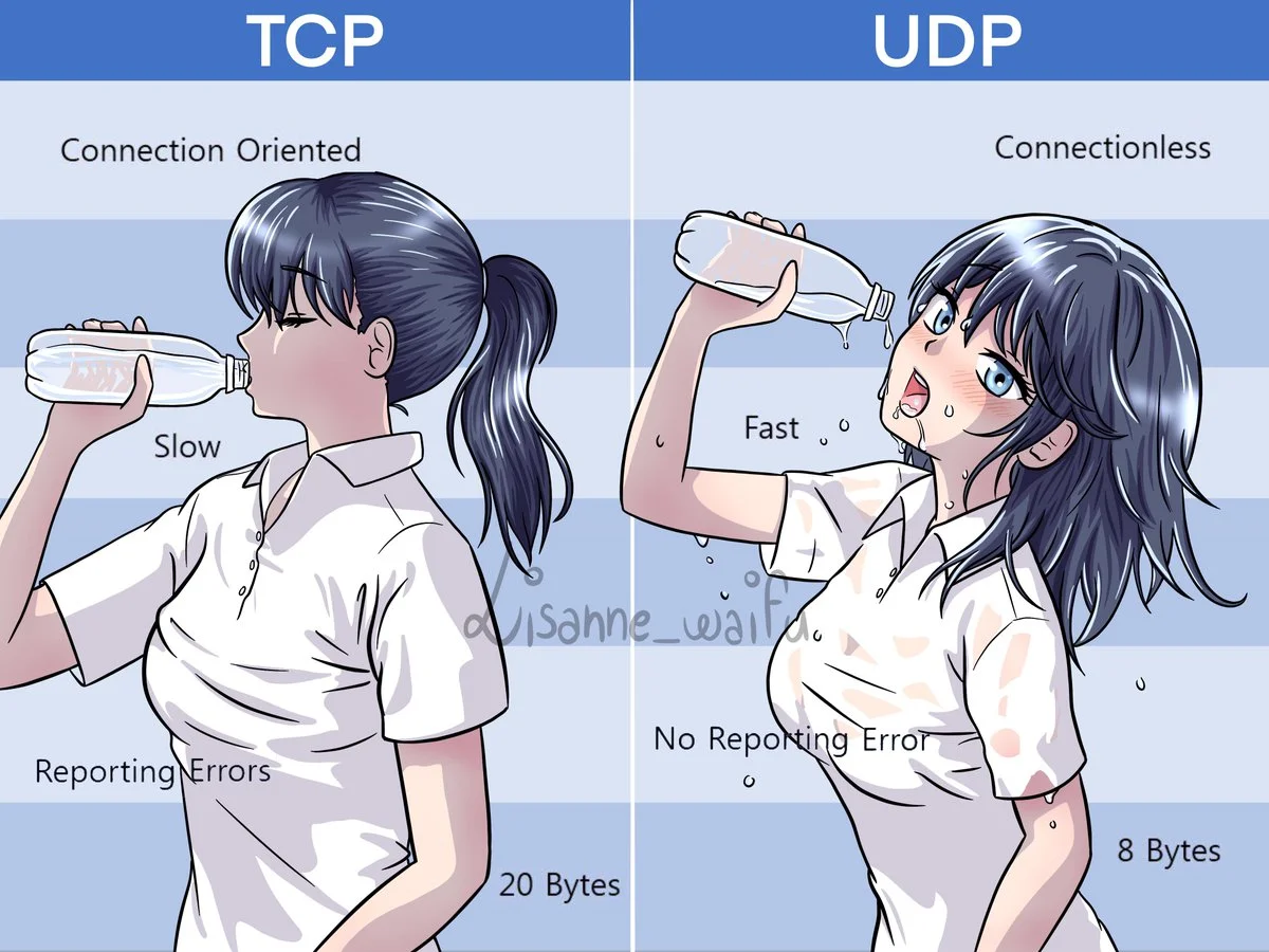
This layer is to determine the approach of data transmission (but not do the transmission job actually). The most two common ways are TCP and UDP. To illustrate the difference between them, you can imagining that what approach you will take if you need to convey water from a place to another place?
A message from application might be split into many data packets of transport layer. Whatever TCP or UDP, both of them will wait and receive data until all data packets they need, and then hand in the data to the application layer after combining them together.
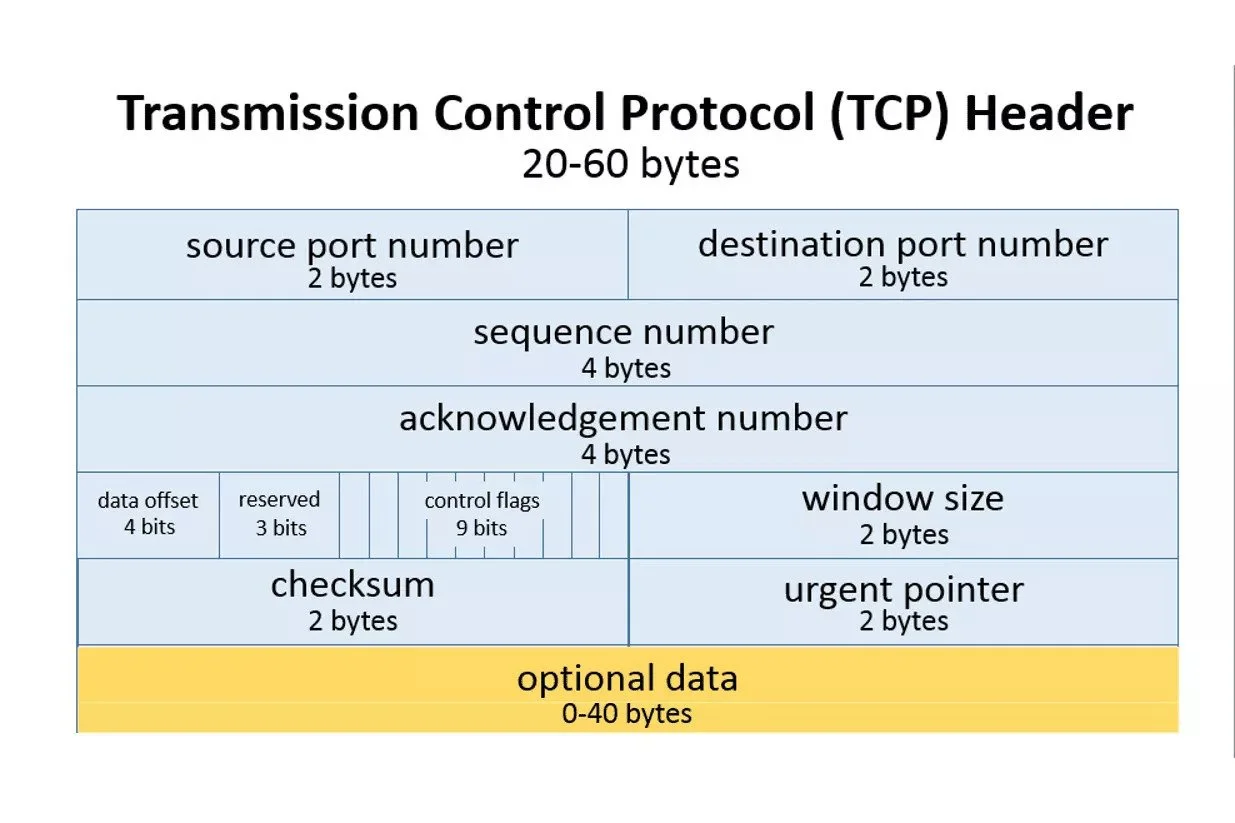
TCP
The way of TCP is building a tube to convey water. Before the transmission, you need to spend some time to build an exclusive tunnel. Once the tunnel is done, the transmission begins. However, once the tunnel is broken, the transmission will be interrupted immediately, it won’t work until you fix the tunnel. All water you need to convey is in the tunnel, so they will safely get the destination following the order. Ideally, if the pipe is large enough, you can convey much water in a short time.
All data from application layer will be added a TCP header, and then the data of application layer becomes the data of transport layer.
UDP
The way of UDP is using high-pressure water gun to shot water to the destination directly. Comparing with TCP, there’s no preparation steps, which means you can start the transmission job as soon as possible. There will be many water guns, even one or many of them are broken, the transmission still works. However, no one knows whether water can get the destination safely and you cannot determine the order of reach of water neither. If there are too many water guns, the environment will be mass.
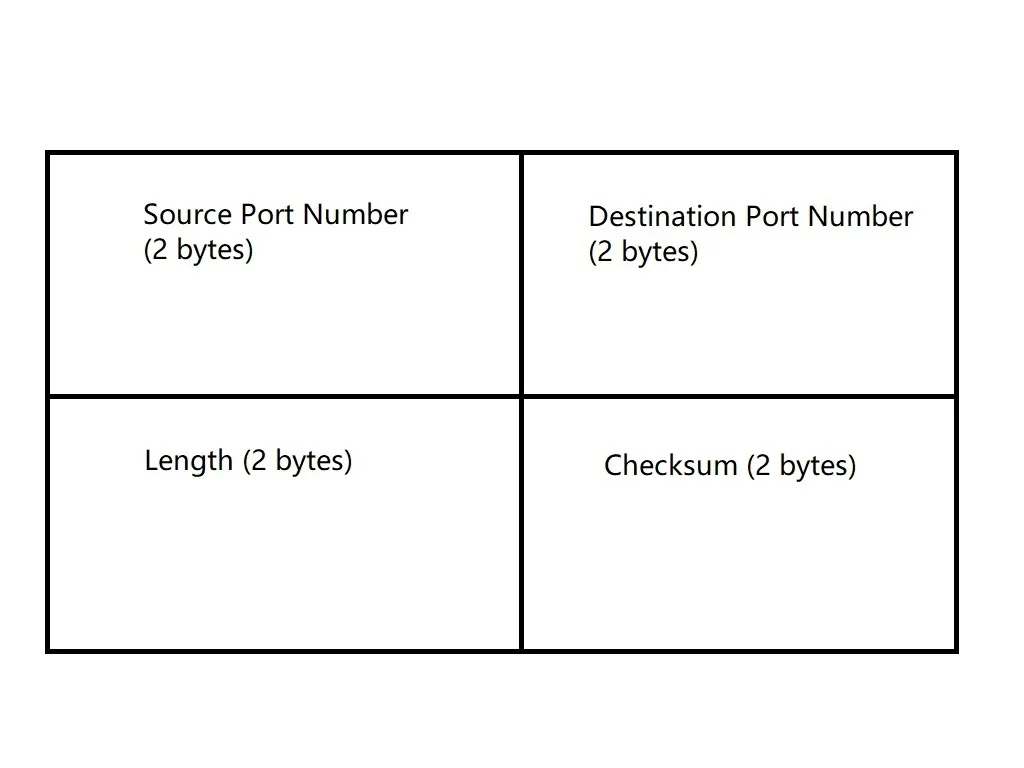
Same to TCP, all data from application layer also need a udp header, but udp header is much eaiser and lighter than tcp’s.
There is a vivid image to illustrate their differences:
Port
Just like host in the application layer, the identifier of transport layer is port. Our device have many ports, just like there are many doors in a big house. Each door will connect to room, and your program runs there, which means you can open the door and communicate with it. There’s one thing worth to note: whether the request from remote or local, they all use port to communication.
Internet Layer
Internet layer is for communications between computers, and IP address works on this layer. As the name address, which means IP indicates the place of the server. Imaging that access a service is like getting something from somewhere, at least, you need to know the position of the destination.
ICMP is an protocol works on this layer, which is used to test the connection between local and remote host. You just need to type command ping <the destination> in your terminal, and then you will get:
|
|
Responsibilities
Packing
It includes packing and unpacking. When you want to send messeges to somewhere, it will pack the data from trasport layer by adding an internet layer header, proving the source and destination of the packet, just like all package nees to be tagged before sending. When you get message from somewhere, the internet layer will unpack the packet, identify the destination and source of the packet. After removing the internet layer header, the packet will convey to the transport layer if necessary.
Transmitting
A data packet from transport layer might be split into multiple data packet of the internet layer. Just like what udp did, the process of transport is not reliable because the cost will be too high (high latency and low speed) if you do the check for all process all the time. Also, there is no connection either, which means all packets won’t reach the destination in order (wow, then the process of transmitting works like udp!).
Route
If you want to drive to somewhere, usually there will be more than one path you can choose, while the same for the packets of internet layer. All route device will make decision on choosing which way according to the current network congestion and the destination of data packet, which means even packets are from the same data packet of transport layer, they might use different ways to get destination. Route in this layer means find the best way to go.
IP Address
There are many protocols works on network layer, but the most important one is Internet Protocol, we called it IP. Nowadays, there are two kinds of IP we are using commonly, IPv4 and IPv6.
IPv4
IPv4 was release on January 1983, which is pretty old now. Although it’s commonly used for today, it likely be replaced by IPv6 someday.
We use IPv4 address to present the location of the device on the internet in IPv4, and its length is 32 bits, which comprises 4 groups of number that between 0 and 255. Since the IP address indicates the address of the device in network, once the device connect to another network, its IP address might change. If a device connects with more than one network, it will also have more than one IP address, of course, they are unique for the device.
The nature of IP address is number, so it could be presented in binary, decimal and hex.
|
|
For easy to read, usually we use the decimal format, like 129.3.3.26.
32 bits are divided into two parts: prefix and suffix. If the length of prefix is n, then the length of suffix is 32-n, n could be any nature number between 0-31.
- prefix defines the network (which network am I in?)
- suffix defins its location in the network (where is my place in the network?)
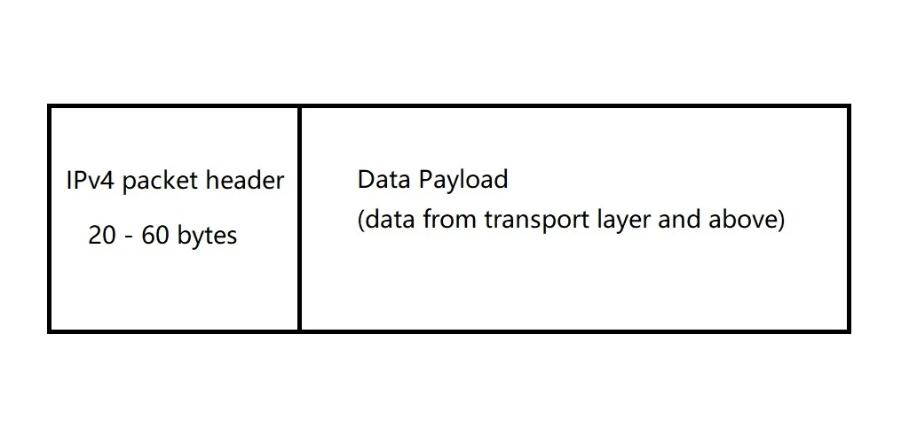
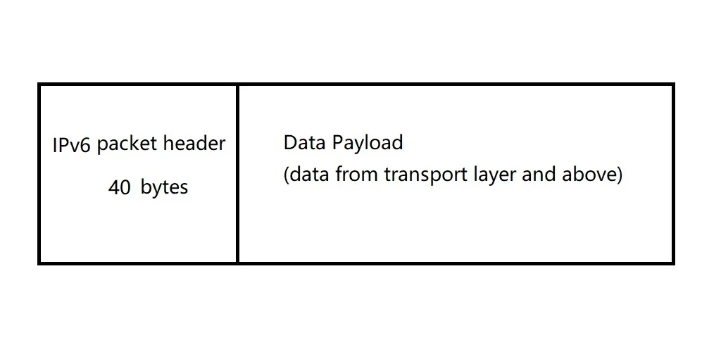
The length of header of IPv4 packet is 20-60 bytes, which includes all necessary information of route.
IPv6
Comparing with IPv4, IPv6 provides a much larger range of IP address, which means the length is longer, 128 bits. The address of IPv6 is presented in hex, like:
2001:8003:e0ac:c800:49c6:bee7:ef2e:4160. All 128 bits are divided into three parts: organization (who owns the address), subnet (which subnet of the organization) and host (where is the place in the subnet)
Link Layer
It also called Network Interface Layer, and it is the lowest layer of TCP/IP. It defines the transmission medium and how the transmission on specific medium. The same netwrok might have more than one transmission medium, for example, in the LAN of your home, your computer connects the LAN using net cable, and your phone connects the LAN using WIFI.
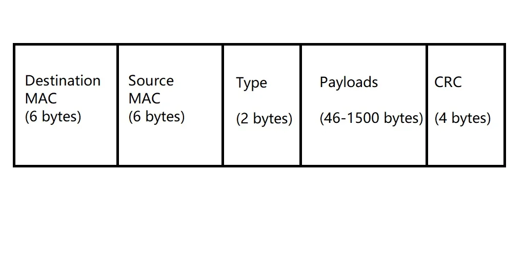
At begining, let talk about MAC address. Unlike IP address, MAC address is given by the manufactor, which is unique around the world. When your device connect to a router, the router will detect that a device come in, and it will read the MAC address of the device. Then the router will allocate an IP address for the mac and record the mapping relation between MAC and IP. Within the same LAN, data transmission is primarily based on MAC addresses rather than IP addresses. The length of MAC is 48 bits, which is represented in hex, like 00:00:0A:BB:28:FC.
Techniques in Link Layer
Ethernet
Ethernet is the technique commonly used in wired LAN. The technique was developed in 1970s, and it has been upgraded for many times until now.
- Standard Ethernet (10 Mbps)
- Fast Ethernet (100 Mbps)
- 1000 Mbps Ethernet
- 10 Gigabyte Ethernet
WIFI
WIFI is the technique commonly used in wireless LAN, which means the transmission medium is air. WIFI is scalable, if there are enough wifi signal transmitter, the signal will cover a large space.
Bluetooth
Bluetooth is another wireless LAN techniques, but it is designed to work for small scale network, so it’s hard to extend. However, because of its low battery consumption, it could be integrated in tiny devices.
Cellular Network
The most common technique on mobile phone. It divided the earth to many different service blocks, and each base station work for a block. When the user moves to another block, there will be another base station that serves for the user.
Digital/Analog Conversion
| From | To | Explanation |
|---|---|---|
| Digital | Digital | the raw data is digital, and transmit in digital signal |
| Digital | Analog | the raw data is digital but transmit in analog signal |
| Analog | Digital | the raw data is analog but transmit in digital signal |
| Analog | Analog | the raw data is analog and transmit in analog signal |
Transmission Medium
All transmission mediums could be divided into two groups, wired and wireless.
| Type | Examples |
|---|---|
| Wired | Twisted Pair, Coaxial Cable, Fiber Optic |
| Wireless | Radio Waves, Microwaves, Infrared Waves |